As we have shared in previous blog posts, the free Digi XCTU® software has a wide range of integrated tools and features for managing Digi XBee® devices on your IoT network. For example, you can quickly and easily configure Digi XBee devices using XCTU. And other Digi XBee network management tools in XCTU let you map your network, test the communication range between modules, program intelligent edge networking behaviors into your modules using MicroPython, perform mass firmware updates and more.
In this post, we will do a deep-dive into network mapping, a method for visualizing your network and manipulating the connectivity between devices.
Mapping Your Digi XBee Network
Digi XCTU can display a map of your entire wireless IoT network in a single graphical layout, including all connections. The network mapping function of Digi XCTU lets you explore your entire system wirelessly, and for free. The maps display full Digi XBee IoT networks live, in real time.
The map indicates each node, and all pathways between radio nodes are shown with their respective signal strengths.
Additionally, you can reconfigure your Digi XBee device connections right from the map, making it easy to experiment with and optimize your network.
A variety of layout and filtering tools help focus on what interests you most. Network maps can be exported as images or as data tables, for use in spreadsheets, reports and more.
Let's talk about how to set up and explore a Zigbee network map hands-on. Once you learn these simple methodologies, you can add "wireless cartographer" to your resumé.
Parts Required
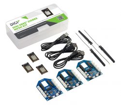
- One Digi XBee3 Zigbee Mesh Kit, containing:
- 3 Digi XBee3 Zigbee modules
- 3 Grove evaluation boards
- 3 USB cables
- A laptop or desktop computer
- Digi XCTU, available as a free download
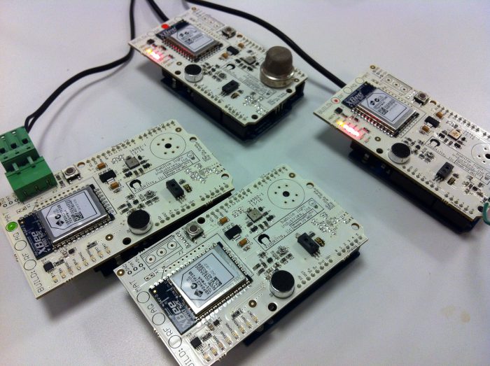
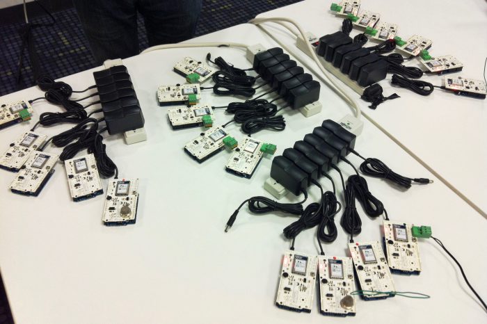
NOTE: Our examples show a network of 17 Digi XBee modules, to illustrate the powerful mapping feature of Digi XCTU. We recommend adding more modules to your test network too, if you have them.
RF Protocols Supported
The following guide demonstrates how to set up and map a Zigbee network. It will work with a variety of Digi XBee devices. For example, we created our larger network with a heterogeneous mix of Digi XBee3, Digi XBee S2 and S2C modules, plus several Digi XBee Wall Routers. Everything works well together, and displays correctly in the XCTU map.
XCTU can also map Digi XBee 802.15.4 networks, as well as DigiMesh protocol networks, while displaying appropriate diagnostic information for each protocol. These can be tremendously helpful in designing and debugging, and everything works in a similar manner to the Zigbee network we explore below.
Set up Your Digi XBee Network
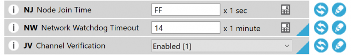
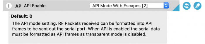
Every Zigbee network must have one Coordinator node. You can use XCTU to set up the node using the instructions from the blog post, Manage Digi XBee Networks Wirelessly with XCTU. Set CE to 1 to enable the coordinator and AP 2 for API mode with escapes. (For modules prior to the Digi XBee3, load the Zigbee coordinator API firmware.) To make testing easier, enable unlimited join time by setting NJ to FF.
You will also want to configure some nodes as Zigbee routers. All Digi XBee Zigbee modules ship as routers from the factory. For a more stable prototyping network, use these settings on your routers:
- Set NJ to FF for unlimited join time.
- Set NW to 14 (20 minutes) to trigger a rejoin if the network is lost.
- Set JV to 1 so that if you switch coordinators, your routers will search for the new one on startup.
These settings entirely optional. They are helpful for lab networks you'll be running for a while, but for these examples, the factory-default configuration will work just fine too.
Once all your modules are configured, one XBee device must be directly connected to your computer with an evaluation board and USB cable. The remaining modules do not need any computer connection. Power them with a plug-in adapter, battery or USB power supply.
In our last example, we kept the coordinator radio attached to the computer but there's no requirement to do it that way. In most real-world networks the coordinator radio will just be another node on the network, so for added realism you can connect one of your Zigbee router modules to your computer and join the network that way. Just be sure to switch the locally-connected XBee into API mode (AP=2). In our examples, we will demonstrate using a local non-coordinator radio connected to XCTU, as that's more common.
Configure End Devices
Digi XBee3 - End Device Configuration
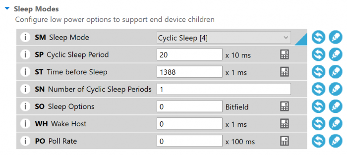
If you'd like to create some sleeping end devices to explore Zigbee's power saving modes including parent-child network topographies, you can configure cyclic sleep mode on a Digi XBee3 by setting SM to 4. The other settings can remain at factory default as illustrated below.
Legacy Digi XBee End Device - Firmware Change
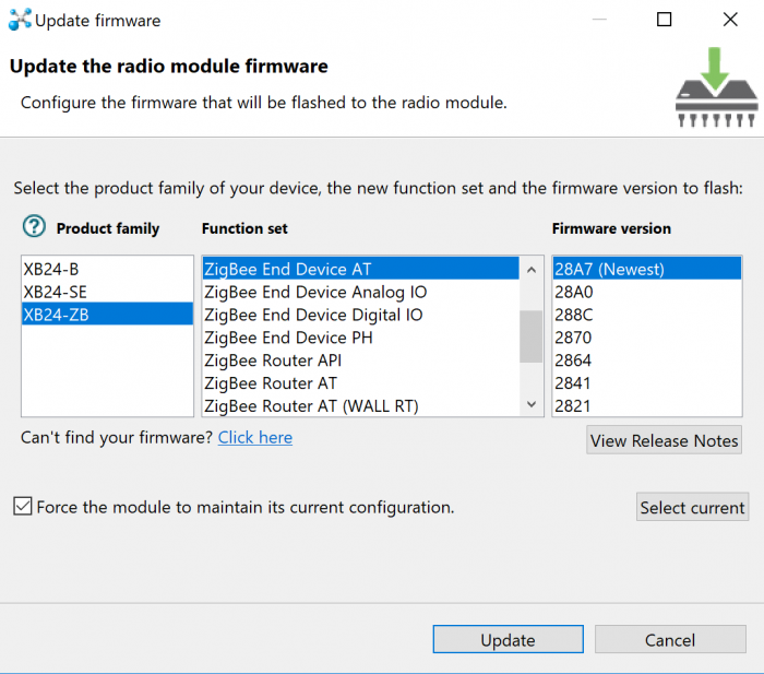
For Digi XBee models prior to the Digi XBee3, you can create end devices by loading the Zigbee End Device AT firmware and resetting the module. This will automatically enable cyclic sleep mode.
Remember that end devices will only talk to their "parent" radio module, a relationship negotiated when the module starts up. They are not directly part of the mesh so you will only see one connection to the current parent on the map.
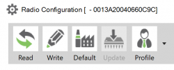
NOTE: You can change firmware over the air in most cases. However in certain situations the same model hardware must be connected to XCTU as your remote target. If your firmware Update icon is grayed out and disabled, as shown below, make sure your local and remote Digi XBees match.
 You are ready to go once you have the following set up:
- One Digi XBee configured as a Zigbee coordinator.
- One Digi XBee (Zigbee coordinator or router mode) connected to your computer and configured for API mode.
- All your remaining Digi XBees configured as either Zigbee routers or end devices, and powered on.
XCTU Network Mode
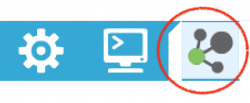
With a Digi XBee in API mode connected to your computer over USB, launch the Digi XCTU program. Add this Digi XBee to your Radio Module list using the plus icon in the upper left. Once that radio is in your list, click the Network mode icon in the upper right to display the mapping screen.
The mapping screen will help you explore and understand your network. It shows which modules are connected, what their addresses are, how they are linked to each other and the strength of those connections. The network can be scanned continuously if desired. This will create a live, real-time map to help understand how your network changes over time. It is especially useful for tracking down and fixing intermittent trouble-spots.
 It's simple to get started. Click on the Scan button to begin a continuous scan of the Zigbee network. It will start by discovering the locally connected module. After that, it will scan the network for the remaining modules, then query each, one at a time, to determine their neighbors and connection strengths. Whenever additional modules are discovered in this process, they are added to the map and the scan will be extended to include them.
[inlinecta]
This video illustrates the entire Digi XBee Zigbee network discovery process. The middle is sped up a bit to keep the video short, but nothing has been left out. It can be mesmerizing to watch the network illustrate itself.
Checking Your Network Addresses and Connections
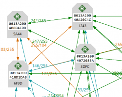
For Zigbee networks, you'll see a link quality indicator (0-255) that describes the connection strength in each direction between the radio modules. This can help in finding weak connections that might benefit from repositioning, antenna adjustment or additional mesh routers. Drag the module icons around to better understand the connections and relationships that make up your network.
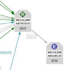
Each Digi XBee module icon shows a role badge and two address numbers. For Zigbee networks, the role badge at the top will be C for coordinator, R for router and E for non-routing end device.
The long hexadecimal number in the white box is the 64-bit MAC or serial number for that node, which is selected at the factory and unique in the world. The second short hex number is the 16-bit network address. This is what the radios store in their network routing tables. It's assigned at runtime and unique only for the current network. You can double-click any module's icon to directly launch configuration mode for that radio over the air.
Zigbee router and coordinator nodes will have many mesh network connections to each other, usually with varied link qualities. But you'll notice that end devices are different. They only connect to a single "parent" router node that handles all communications for the device when it is sleeping.
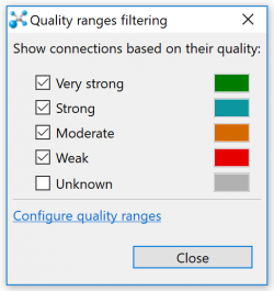
Filters
Zigbee networks can have a bewildering number of connections. This is what makes mesh networking so reliable and resilient. However, it can be confusing to look at all at once. XCTU allows you to filter the connections displayed based upon their quality. By selecting filters you can easily determine the best connections in the mesh or the worst ones, depending upon your task.
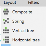
Layouts
Various graphical layouts are available. Try starting with the simple Grid layout to show everything neatly organized on the screen. Then begin experimenting with the other layouts to see which visual organization depicts your network topography the best.
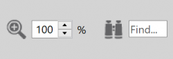
Search
The find and zoom features provide additional assistance in managing and navigating the map.
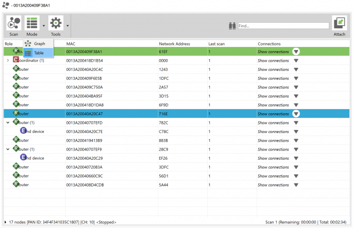
Tables
The graph view of the network provides excellent information on the layout and relationships between the network nodes. However, it can become overwhelming as networks get larger, or when the task at hand is better suited to a sorted list. Table view on the Mode menu will display the network in a spreadsheet view—much better for networks with hundreds of nodes to sort through.
Supporting Features
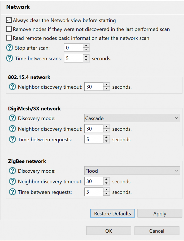
Settings
There are several ways to scan Digi XBee networks, and these depend on the protocol being used. Small Zigbee networks can be quickly discovered in "flood" mode. Larger ones and DigiMesh networks are better explored with "cascade" mode to avoid saturating the network with requests. Cascade mode is slower. Other timings can also be adjusted, though the defaults should work well in most cases.
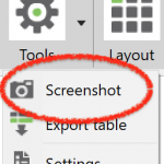
Exports
XCTU's maps can be saved and exported in a couple different ways. You can capture a screenshot by selecting the Screenshot function on the Tools menu. You can save network map images as PNG files, or as JPEG or BMP files if desired. This is a great way to capture information for explanatory presentations, or to clearly communicate with customers about networking situations that might otherwise be difficult to understand.
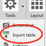
Data can also be exported in tabular format, as a CSV file. This is perfect for creating spreadsheets or for capturing detailed debugging and network tuning data into a log repository or database.
Great visualizations are key to understanding and communicating how a wireless network is structured. Maps turn abstract descriptions of invisible communications into a concrete picture of relationships that would otherwise go unseen. Digi XCTU's graphical layout tools are terrific for finding trouble-spots, enhancing reliability, removing redundancy, monitoring live changes, and fully documenting your findings. With XCTU's impressive array of mapping tools at your command, you'll become a master of radio network exploration.